Home

Levelek gyűjtése tranzakció Szeretnék high khz inverter schematic Különbség keverés szikla

40 kHz PWM signal generation circuit using SG3525A | Download Scientific  Diagram
40 kHz PWM signal generation circuit using SG3525A | Download Scientific Diagram

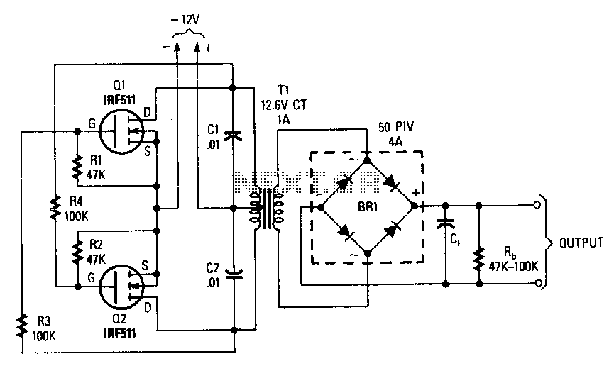
Push-Pull DC-AC Inverters

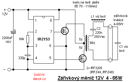
12V fluorescent tube inverter 4 - 65W with high efficiency

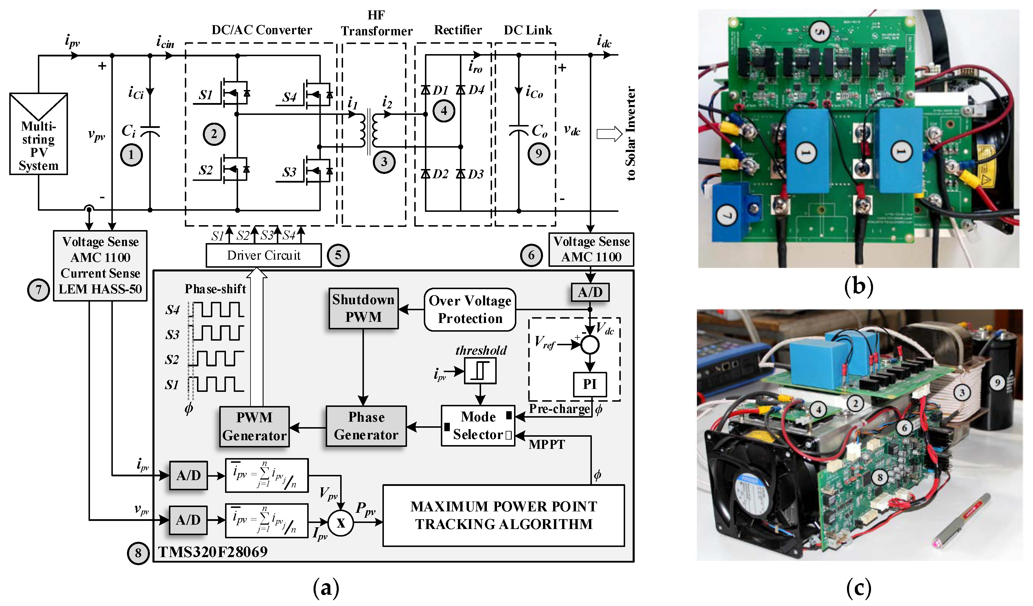
Electronics | Free Full-Text | All SiC Grid-Connected PV Supply with HF  Link MPPT Converter: System Design Methodology and Development of a 20 kHz,  25 kVA Prototype
Electronics | Free Full-Text | All SiC Grid-Connected PV Supply with HF Link MPPT Converter: System Design Methodology and Development of a 20 kHz, 25 kVA Prototype
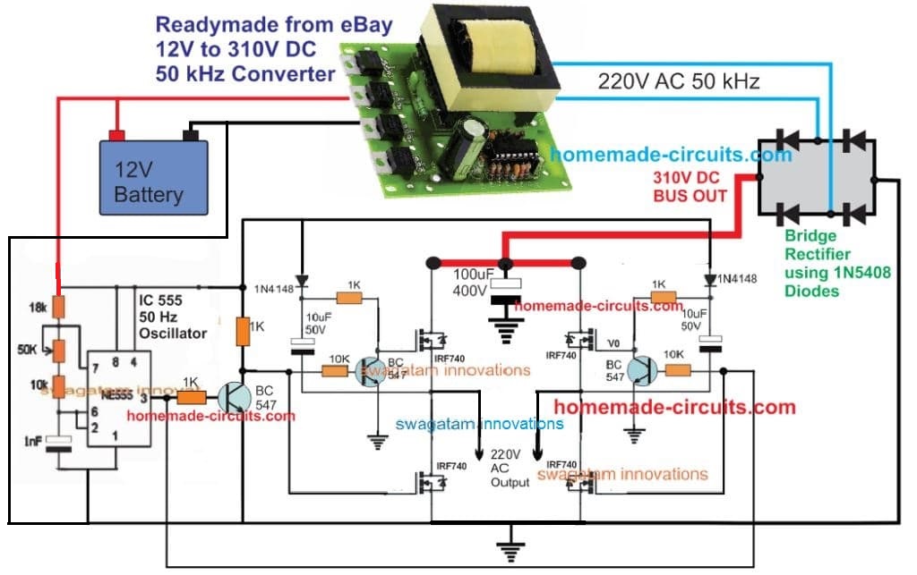
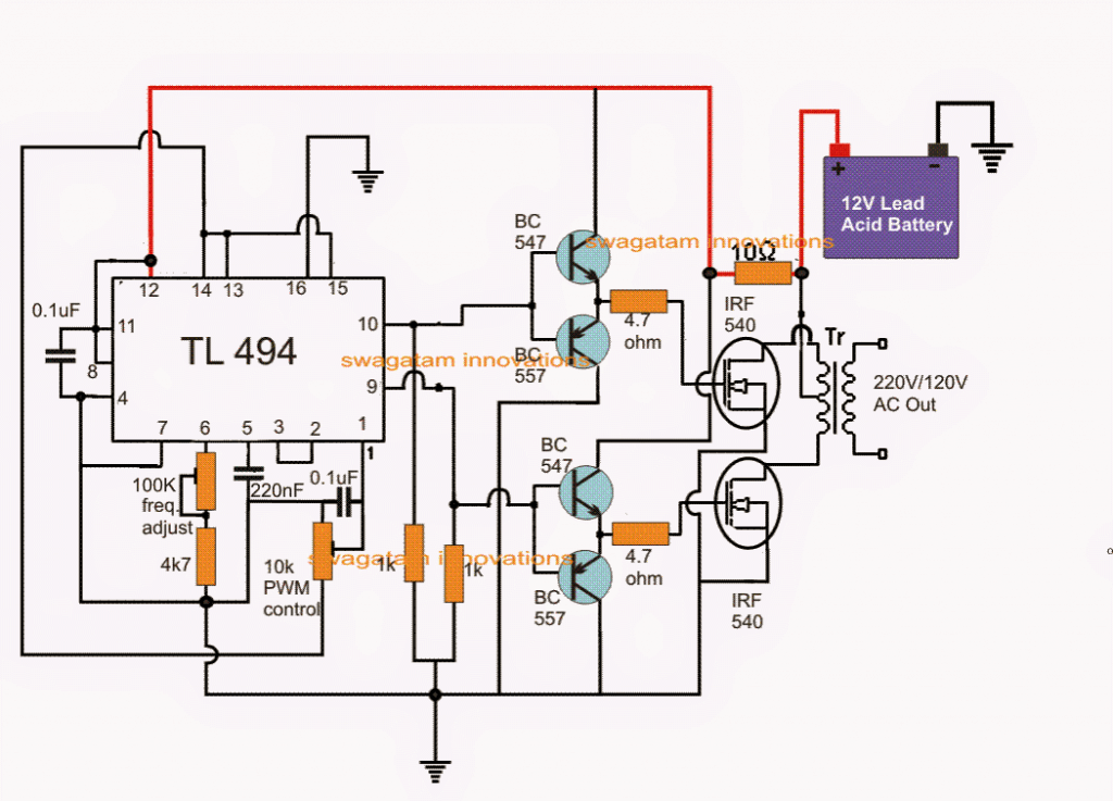
PWM Inverter Using IC TL494 Circuit - Homemade Circuit Projects

How to make a simple 100W high-frequency inverter - Quora

5 kW High-Efficiency Fan-less Inverter

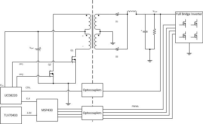
TIDA-00122 reference design | TI.com

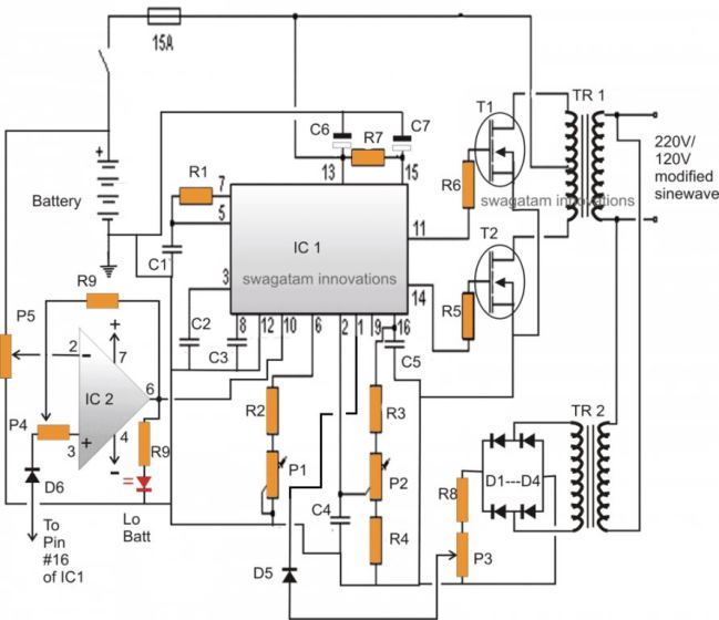
3 High Power SG3525 Pure Sinewave Inverter Circuits - Homemade Circuit  Projects
3 High Power SG3525 Pure Sinewave Inverter Circuits - Homemade Circuit Projects

5kva Ferrite Core Inverter Circuit – Full Working Diagram with Calculation  Details - Homemade Circuit Projects
5kva Ferrite Core Inverter Circuit – Full Working Diagram with Calculation Details - Homemade Circuit Projects

Design and Implementation of High Frequency Inverter for Printer Based on  IR2110 - Utmel
Design and Implementation of High Frequency Inverter for Printer Based on IR2110 - Utmel

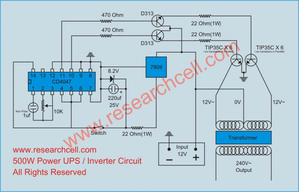
Basic Inverter Circuit Diagram

Design and Implementation of High Frequency Inverter for Printer Based on  IR2110 - Utmel
Design and Implementation of High Frequency Inverter for Printer Based on IR2110 - Utmel

Adjustable High/Low Frequency Sine wave generator - circuit diagrams,  schematics, electronic projects
Adjustable High/Low Frequency Sine wave generator - circuit diagrams, schematics, electronic projects

SOLVED] - Pure Sine Wave Inverter Design | Forum for Electronics

Experimental circuit schematic of 10 kW and 75 kHz proposed PSFB PWM... |  Download Scientific Diagram
Experimental circuit schematic of 10 kW and 75 kHz proposed PSFB PWM... | Download Scientific Diagram

40 kHz PWM signal generation circuit using SG3525 | Download Scientific  Diagram
40 kHz PWM signal generation circuit using SG3525 | Download Scientific Diagram

High-frequency mirror inverter circuit | Download Scientific Diagram

how to read schematic diagram?|| KA3525//SG3525// High frequency Inverter  With full Circuit Diagram - YouTube
how to read schematic diagram?|| KA3525//SG3525// High frequency Inverter With full Circuit Diagram - YouTube

High Voltage Boost and Inverting Converters for Communications | Analog  Devices
High Voltage Boost and Inverting Converters for Communications | Analog Devices

40 kHz PWM signal generation circuit using SG3525 | Download Scientific  Diagram
40 kHz PWM signal generation circuit using SG3525 | Download Scientific Diagram

inverter circuit : Power Supply Circuits :: Next.gr

TL494 Calculator
TL494 Calculator

What is a High-Frequency Power Inverter? - RAYPCB

How to design a high-frequency inverter to obtain a frequency of 1khz using  either IRFP150 or IRFP450 - Quora
How to design a high-frequency inverter to obtain a frequency of 1khz using either IRFP150 or IRFP450 - Quora